Canvas Operations
We are committed to providing a seamless and intuitive diagram-building experience. We carefully designed features and operations to enhance clarity, improve accessibility, and make working with the canvas effortless. Whether you’re constructing complex systems from scratch or beautifying existing diagrams, our canvas functionalities are here to support your creativity and efficiency.
1. Automatically connect new nodes by double clicking
If you want to be faster when adding new components to your diagram, you can leverage the automatic connect feature to place them directly in the desired position on the canvas. Since the connection is built automatically, you can influence its direction and type by pressing the dedicated keyboard shortcuts. You can read more on our Framework Basics page.
- SHIFT – creates a top connection;
- CTRL – creates a down connection
- SHIFT + CTRL – create a left connection
- Moreover, holding ALT with any other shortcut will create a state connection between the two nodes;
To automatically create a new node and an adjacent connection, you must:
1. Select the origin node (already present on the canvas);
2. Double-click on a compatible node in the toolbar;
3. (Optional) Use keyboard shortcuts to modify the position of the new node;
4. Notice that the node from the toolbar is automatically linked by the origin node and added to the canvas;
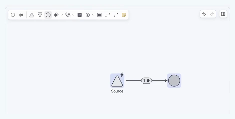
The auto-connect tool will detect adjacent node anytime you would wish to connect multiple outputs from a single source note. As such you can simply double click to activate auto-connect and the new node will be placed next to existing nodes to avoid overlapping.
2. Use Auto-link for loose connections
When just creating a connection or when an endpoint of a connection is deleted, you are able to easily connect a new node by dragging it over the loose connection point. A loose end is marked with a small ring; drop a node from the toolbar onto it and the node is connected automatically. Moreover, you can activate the auto-link anchor point on both the origin and the target of any loose connections
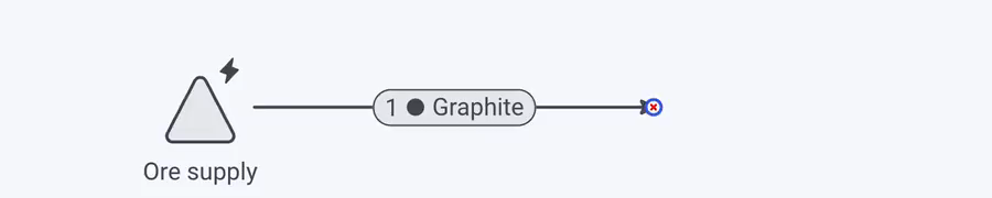
To avoid potential structural issues the auto-link anchor point will be highlighted red for incompatible nodes, and the end of a connection dropped onto one of them is marked with a red cross. A node is classified as incompatible for the following scenarios:
- The node is always an origin for resource connections – Sources
- The node is always a target for resource connections – Sink
- The node can be connected only via state connections – Registers, End Conditions
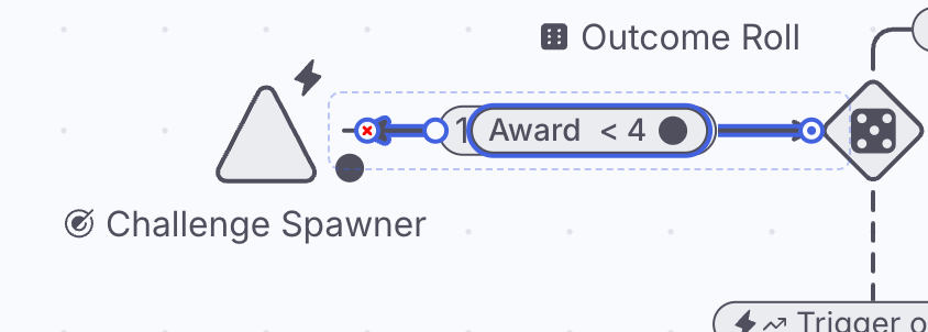
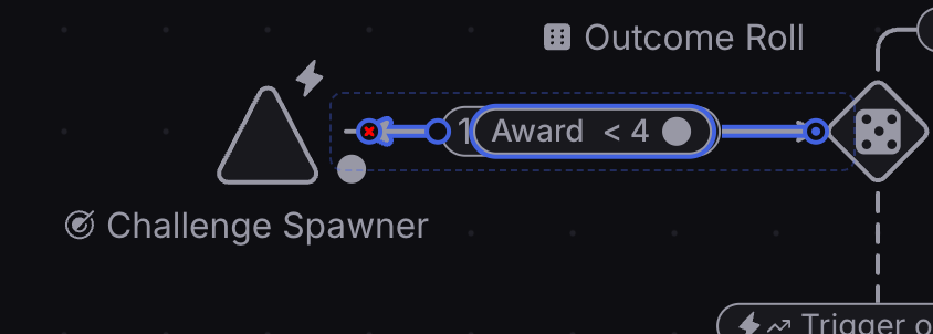
3. Duplicate/Delete with Connections
For multiple scenarios, systems designers might want to model similar functionalities to existing ones in their diagram. To make this action as simple as possible, you can use the option Duplicate with Connections.
1. Select a node or a group of nodes;
2. Right-click on your selection to open the contextual menu;
3. Select “Duplicate with connections”
4. Notice that the entire selection is duplicated alongside the linked connections. The new connections are also connected to their existing origin nodes to ensure that the duplicated system uses the same values as the original one;
Using “Delete with connections” is similar to the duplicate functionality, as the selected components will be removed alongside any resource or state connection with their origin or target points linked to the selection.
Additionally, you can use the keyboard shortcut CTRL/CMD + SHIFT + D for duplicating with connections and CTRL/CMD + Backspace for deleting with connections.
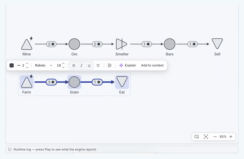
4. Highlight connected nodes
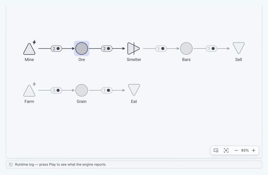
When a diagram increases in complexity and multiple subsystems interact, it can be difficult to keep track of the connections between different systems in the model. To aid with this problem, Machinations offers the functionality Highlight connected nodes, which improves visibility for selected nodes and all connected components.
When using the highlighting feature,e you are able to select the desired level of relation to the original node. As such, when selecting the first level only nodes connected by a single connection will be highlighted, however, for level 3, all chains of 3 connections will be showcased. Moreover, if the diagram contains multiple disconnected systems, the highlighter fades every component that is not connected to your selection, like the Farm subsystem in the recording, so that only a single subsystem stays in color. A chip in the toolbar names the level in use (for example 3 levels) and has a cross to switch the highlight off.
To activate the highlight feature, right-click on your desired node, select “Highlight connected nodes” and choose your desired level of relevance.
5. Snap to grid and align with guides
The canvas Grid and Guides will help you to align your constructions automatically. When moving things around on the canvas, you will see blue guides that indicate and line up to the position of the nearest components. Moreover, using the canvas grid (colored dots) will ensure that nodes can be equidistant and symmetrical and connections follow straight lines.


6. Custom multiple selection
When diagrams increase in complexity and size, modifying specific components can be tedious and time-consuming. As such, we have built the option to create a custom multiple selection containing only the desired nodes. Once the selection is created, the properties panel will display all the common fields of the selected nodes, and all their properties can be changed at once.
To create a custom selection, right-click an empty part of the canvas and open Select. The menu lists every type on the canvas with its count (for example Pool (3) or Resource Connection (6)); tick one or more types to select all of those components at once. Select nodes, Select connections and Select all are in the same menu.
All the custom selections are applied only for the Selected Layer. To select nodes from multiple layers use the rubber band multiple selection by dragging the cursor over the canvas.
7. Add nodes using the Building Wizard
To enhance the experience and efficiency of creating models, you can use the diagram-building wizard to automatically create and connect components similar to the auto-connect double-click feature. To check out multiple methods of adding nodes to canvas, check out the following page: Framework Basics.
After selecting a node, small arrows appear around it. Hover an arrow to open the wizard, one small panel. Use the Resource | State switch at the top to choose the kind of connection, then click the type of node to add: one click builds it, already connected, on the side of the arrow you used. A short Setup follows, where you name the new node and set the connection’s one value, and then press Done. Back removes the new node and its connection so you can choose again.
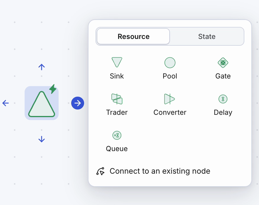
To connect two existing nodes, hover an arrow and choose Connect to an existing node, then click the target node. You can also drag from one of the surrounding arrows toward the target node.
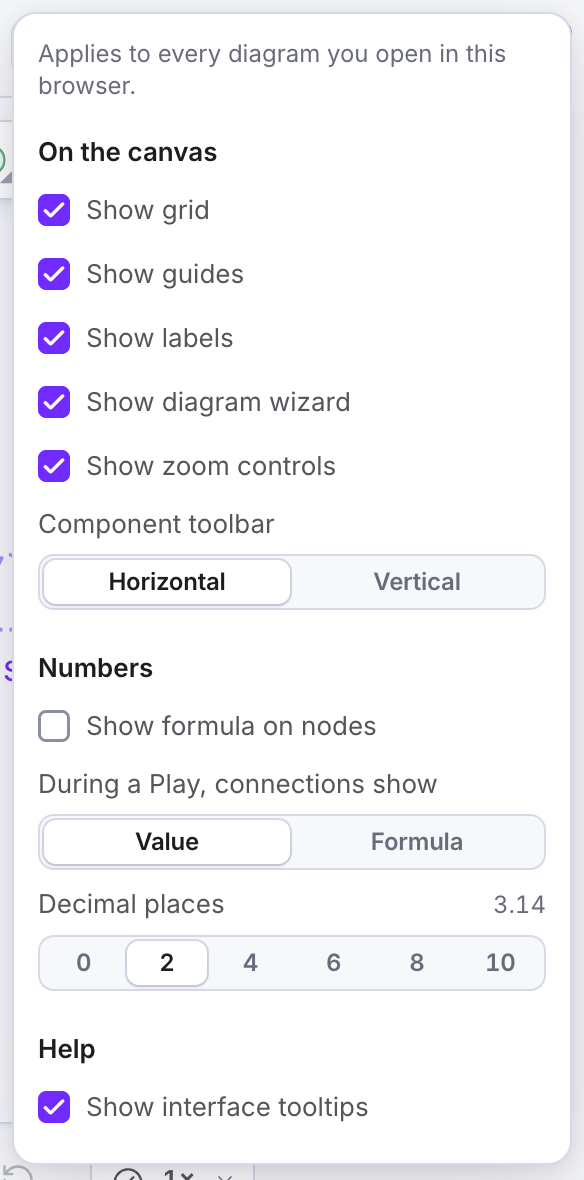
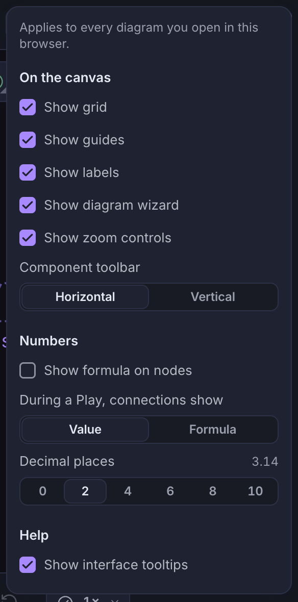
You can turn the wizard on or off with Show diagram wizard in View options (the settings button at the right end of the header).
8. Copy and Paste Components Between Diagrams
Whether you are following a tutorial, adjusting a template, or using community diagrams, the canvas allows you to copy and paste any components between multiple diagrams. Simply create a multiple selection, press the keyboard shortcut, or click on copy on the context menu, and you can paste the nodes and connections on your new diagram.