State Connections

 State Connections (Alt+C) can change how other nodes and connections behave as the diagram state changes.
The state of a Machinations diagram refers to the current distribution of Resources among its Nodes. When Resources are generated or redistributed, the State of the diagram/system changes.
Properties
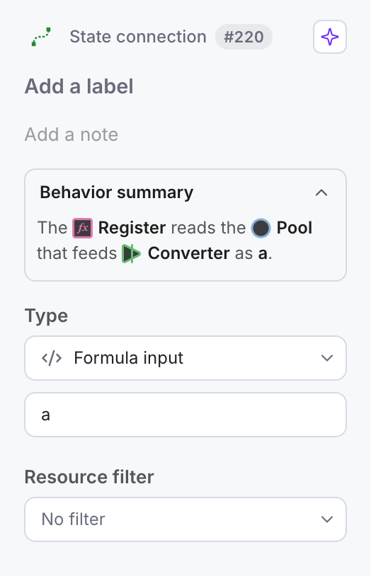
Select a State Connection to adjust it in the Properties panel on the right: its label and note, Type (set to variable in the screenshot, with the box below holding the formula), Resource filter and Lever. Color and line width are on the floating toolbar above the connection. The choices in the Type menu depend on what the connection joins: a trigger fires the target on the next Step when the origin acts, and a condition is active while the origin’s value passes a comparison such as “greater than 0”.
A Change value or Change interval connection also has Force update disabled target: when it is on, the change still lands while the target is disabled.
We will explain these properties below.
Label
Click Add a label to add descriptive text or annotations; Add a note below it holds a longer description. This will make it easier to identify the purpose of the connection. It is also good practice and will make your diagram more accessible to others.
Formula
State Connections allow you to modify the flow rates of Resource Connections or to trigger Nodes to fire, activate or deactivate them in response to changes in Resource distribution.
The Formula on a State Connection indicates how or under which conditions a target Node or Connection is or will be changed.
You may use Parameters (called Custom Variables in older guides), and functions from the math.js library in the Formula field.
The default formula value of a State Connection is “+1”. This will apply any change in the origin node’s value to the target node.
Please read our State Connections Formulas article to learn more.
Filter
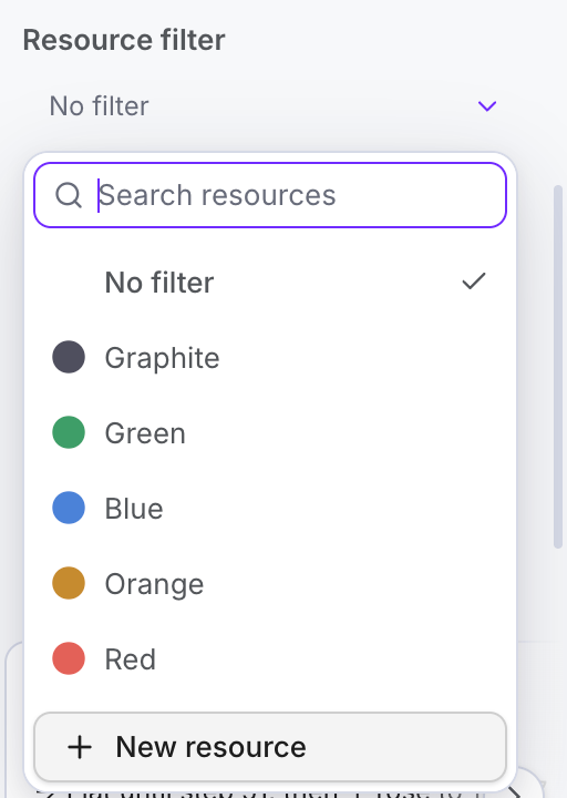
State Connections will respond to Resources based on their color similar to Resource Connections. The Resource filter menu lists the resources of your diagram (and a New resource button) and starts at No filter.
Once the filter is enabled, the formula of a State Connection will only be executed if a Resource with matching color passes through a Gate or Pool.
You can find out more about this in our Filter [Color coding] article.
Examples for different targets
Node as Target
- When a Resource gets to Pool B it activates Source C
Resource Connection as Target
- When the number of Resources in Pool B is >=6 activate the transfer
State Connection as Target
- When Pool B has 3 or more Resources activates add
Composite example
In this example, there are 3 controlling Nodes: Pools B, D, and F.
- Pool B activates Source C as soon it receives a Resource from the automatic Source A.
- When B hits a number of Resources equal to or bigger than 6, it also activates the transfer between Source E and Pool F.
- Pool F is in itself a controlling Node and it will affect the flow of Resources between C and D, by adding +1 each Step.
- Pool D activates the Stop End Condition when it collects 15 Resources. The diagram stops executing.
Types of State Connections
Formulas on State Connections indicate how or under which conditions they change the Target. Please review the following articles to find out more about:
Selected models to Play and remix: Selected feedback loop models.